 Hispanopedia Wiki
Los condensadores se fabrican en una gran variedad de estilos, formas, dimensiones y materiales. Todos contienen al menos dos conductores eléctricos , llamados placas , separados por una capa aislante ( dieléctrica ). Los condensadores se utilizan ampliamente como parte de los circuitos eléctricos en muchos dispositivos eléctricos comunes.
Los condensadores, junto con las resistencias y los inductores , pertenecen al grupo de componentes pasivos en equipos electrónicos . Los condensadores pequeños se utilizan en dispositivos electrónicos para acoplar señales entre etapas de amplificadores, como componentes de filtros eléctricos y circuitos sintonizados, o como parte de sistemas de alimentación para suavizar la corriente rectificada. Los condensadores de mayor tamaño se utilizan para el almacenamiento de energía en aplicaciones como luces estroboscópicas, como parte de algunos tipos de motores eléctricos o para la corrección del factor de potencia en sistemas de distribución de corriente alterna. Los condensadores estándar tienen un valor fijo de capacitancia , pero los condensadores ajustables se utilizan con frecuencia en circuitos sintonizados. Se utilizan diferentes tipos según la capacitancia requerida, la tensión de trabajo, la capacidad de manejo de corriente y otras propiedades.
Si bien, en cifras absolutas, los condensadores que se fabrican con mayor frecuencia están integrados en memorias de acceso aleatorio dinámico , memorias flash y otros chips de dispositivos, este artículo trata sobre los componentes discretos.
Características generales
Construcción convencional

Un condensador convencional almacena energía eléctrica en forma de electricidad estática mediante la separación de cargas en un campo eléctrico entre dos placas de electrodos . Los portadores de carga suelen ser electrones . La cantidad de carga almacenada por unidad de voltaje depende esencialmente del tamaño de las placas, las propiedades del material de las placas, las propiedades del material dieléctrico situado entre ellas y la distancia de separación (es decir, el espesor del dieléctrico). La diferencia de potencial entre las placas está limitada por las propiedades del material dieléctrico y la distancia de separación.
Casi todos los condensadores industriales convencionales, excepto algunos tipos especiales como los "condensadores de paso", se construyen como "condensadores de placas", incluso si sus electrodos y el dieléctrico entre ellos están enrollados o laminados. La capacitancia C de un condensador de placas es
- .

La capacitancia aumenta con el área A de las placas y con la permitividad ε del material dieléctrico, y disminuye con la distancia de separación d entre las placas . Por lo tanto, la capacitancia es máxima en dispositivos fabricados con materiales de alta permitividad, gran área de placa y pequeña distancia entre placas.
Construcción electroquímica

- Capa interna de Helmholtz del IHP
- Capa externa de Helmholtz del OHP
- Capa difusa
- Iones solvatados
- Iones específicamente adsorbidos (pseudocapacitancia)
- Molécula de disolvente
Otro tipo, el condensador electroquímico , utiliza otros dos principios de almacenamiento para guardar energía eléctrica. A diferencia de los condensadores cerámicos, de película y electrolíticos , los supercondensadores (también conocidos como condensadores de doble capa eléctrica (EDLC) o ultracondensadores) no tienen un dieléctrico convencional. El valor de capacitancia de un condensador electroquímico está determinado por dos principios de almacenamiento de alta capacidad. Estos principios son:
- almacenamiento electrostático dentro de las capas dobles de Helmholtz logrado en la interfaz de fase entre la superficie de los electrodos y el electrolito (capacitancia de doble capa) ; y
- El almacenamiento electroquímico se logra mediante la transferencia de carga electrónica faradaica a través de iones absorbidos específicamente mediante reacciones redox (pseudocapacitancia) . A diferencia de las baterías, en estas reacciones, los iones simplemente se adhieren a la estructura atómica de un electrodo sin formar ni romper enlaces químicos, y no se producen modificaciones químicas, o estas son insignificantes, durante la carga y descarga.
La relación de almacenamiento resultante de cada principio puede variar considerablemente, dependiendo del diseño del electrodo y la composición del electrolito. La pseudocapacitancia puede aumentar el valor de la capacitancia hasta en un orden de magnitud con respecto al de la doble capa por sí sola. [ 1 ]
Clasificación
Los condensadores se dividen en dos grupos mecánicos: dispositivos de capacitancia fija con capacitancia constante y condensadores variables. Los condensadores variables se fabrican como potenciómetros de ajuste , que se regulan únicamente durante la calibración del circuito, o como dispositivos sintonizables durante el funcionamiento del instrumento electrónico.
El grupo más común son los condensadores fijos. Muchos reciben su nombre según el tipo de dieléctrico. Sin embargo, para una clasificación sistemática, estas características no son útiles, ya que uno de los más antiguos, el condensador electrolítico, se denomina según la construcción de su cátodo. Por lo tanto, los nombres más utilizados son simplemente históricos.
Los tipos de condensadores más comunes son:
- Los condensadores cerámicos tienen un dieléctrico cerámico .
- Los condensadores de película y de papel reciben su nombre según sus materiales dieléctricos.
- Los condensadores electrolíticos de aluminio, tantalio y niobio reciben su nombre del material utilizado como ánodo y de la construcción del cátodo ( electrolito ).
- Los condensadores de polímero son condensadores electrolíticos de aluminio, tantalio o niobio que utilizan un polímero conductor como electrolito.
- Supercondensador es el nombre de la familia para:
- Los condensadores de doble capa recibieron su nombre del fenómeno físico de la doble capa de Helmholtz .
- Los pseudocapacitores recibieron su nombre por su capacidad de almacenar energía eléctrica electroquímicamente mediante una transferencia de carga faradaica reversible .
- Los condensadores híbridos combinan condensadores de doble capa y pseudocondensadores para aumentar la densidad de potencia.
- Los condensadores de mica plateada, vidrio, silicio, de aire y de vacío reciben su nombre según su material dieléctrico.

Además de los tipos de condensadores mostrados anteriormente, que derivan su nombre de su desarrollo histórico, existen muchos condensadores individuales que han sido nombrados en función de su aplicación. Entre ellos se incluyen:
- Condensadores de potencia , condensadores de motor , condensadores de enlace de CC , condensadores de supresión , condensadores de cruce de audio , condensadores de balasto de iluminación , condensadores de amortiguación , condensadores de acoplamiento , desacoplamiento o derivación .
Often, more than one capacitor family is employed for these applications, e.g. interference suppression can use ceramic capacitors or film capacitors.
Other kinds of capacitors are discussed in the #Special capacitors section.
Dielectrics

The most common dielectrics are:
- Ceramics
- Plastic films
- Oxide layer on metal (aluminum, tantalum, niobium)
- Natural materials like mica, glass, paper, air, SF6, vacuum
All of them store their electrical charge statically within an electric field between two (parallel) electrodes.
Beneath these conventional capacitors a family of electrochemical capacitors called supercapacitors was developed. Supercapacitors do not have a conventional dielectric. They store their electrical charge statically in Helmholtz double-layers and faradaically at the surface of electrodes
- with static double-layer capacitance in a double-layer capacitor and
- with pseudocapacitance (faradaic charge transfer) in a pseudocapacitor
- or with both storage principles together in hybrid capacitors.
The most important material parameters of the different dielectrics used and the approximate Helmholtz-layer thickness are given in the table below.
El área de las placas del condensador se puede adaptar al valor de capacitancia deseado. La permitividad y el espesor del dieléctrico son los parámetros determinantes para los condensadores. La facilidad de procesamiento también es crucial. Las láminas delgadas y mecánicamente flexibles se pueden enrollar o apilar fácilmente, lo que permite crear diseños de gran tamaño con altos valores de capacitancia. Sin embargo, las capas cerámicas sinterizadas metalizadas ultrafinas, recubiertas con electrodos metalizados, ofrecen las mejores condiciones para la miniaturización de circuitos con componentes SMD .
Las cifras de la tabla anterior explican algunos hechos sencillos:
- Los supercondensadores tienen la mayor densidad de capacitancia debido a sus principios especiales de almacenamiento de carga.
- Los condensadores electrolíticos tienen una densidad de capacitancia menor que los supercondensadores, pero la mayor densidad de capacitancia de los condensadores convencionales debido a su dieléctrico delgado.
- Los condensadores cerámicos de clase 2 tienen valores de capacitancia más altos en un caso dado que los condensadores de clase 1 debido a su mayor permitividad.
- Los condensadores de película, con sus diferentes materiales de película plástica, presentan una pequeña variación en las dimensiones para un valor de capacitancia/voltaje dado, debido a que el espesor mínimo de la película dieléctrica difiere entre los distintos materiales.

Capacitancia y rango de voltaje
La capacitancia varía desde picofaradios hasta cientos de faradios. Los voltajes nominales pueden alcanzar los 100 kilovoltios. En general, la capacitancia y el voltaje se correlacionan con el tamaño físico y el costo.

Miniaturización
Al igual que en otros campos de la electrónica, la eficiencia volumétrica mide el rendimiento de una función electrónica por unidad de volumen. En el caso de los condensadores, la eficiencia volumétrica se mide mediante el producto CV, que se calcula multiplicando la capacitancia (C) por la tensión máxima nominal (V) y dividiendo el resultado entre el volumen. Entre 1970 y 2005, la eficiencia volumétrica mejoró notablemente.
- Miniaturización de condensadores
 Condensador de papel apilado de 1923 para el desacoplamiento (bloqueo) de ruido en líneas telegráficas.
 Condensador de papel metalizado bobinado de principios de la década de 1930 en una carcasa de cartón duro, valor de capacitancia especificado en "cm" en el sistema cgs ; 5000 cm corresponden a 0,0056 μF.
 Condensador electrolítico húmedo de aluminio plegado, Bell System 1929, vista del ánodo plegado, que estaba montado en una carcasa cuadrada (no mostrada) llena de electrolito líquido.
 Dos condensadores electrolíticos de aluminio húmedo de 8 μF y 525 V, bobinados en una carcasa de papel sellada con alquitrán, procedentes de una radio de la década de 1930.

Superposición de las aplicaciones
Estos condensadores individuales pueden realizar su función independientemente de su pertenencia a un tipo de condensador de los mostrados anteriormente, de modo que existe un rango de aplicaciones superpuesto entre los diferentes tipos de condensadores.
Tipos y estilos
condensadores cerámicos

Un condensador cerámico es un condensador fijo no polarizado compuesto por dos o más capas alternas de cerámica y metal, donde el material cerámico actúa como dieléctrico y el metal como electrodos. El material cerámico es una mezcla de gránulos finamente molidos de materiales paraeléctricos o ferroeléctricos , modificados con óxidos mixtos necesarios para lograr las características deseadas del condensador. El comportamiento eléctrico del material cerámico se divide en dos clases de estabilidad:
- Condensadores cerámicos de clase 1 con alta estabilidad y bajas pérdidas que compensan la influencia de la temperatura en aplicaciones de circuitos resonantes. Las abreviaturas comunes de los códigos EIA / IEC son C0G /NP0, P2G/N150, R2G/N220, U2J/N750, etc.
- Condensadores cerámicos de clase 2 con alta eficiencia volumétrica para aplicaciones de búfer, derivación y acoplamiento. Las abreviaturas comunes de los códigos EIA/IEC son: X7R/2XI, Z5U/E26, Y5V/2F4, X7S/2C1, etc.
La plasticidad de la materia prima cerámica resulta ideal para numerosas aplicaciones especiales y permite una gran variedad de estilos, formas y dimensiones de condensadores cerámicos. El condensador discreto más pequeño, por ejemplo, es un condensador de chip "01005" con unas dimensiones de tan solo 0,4 mm × 0,2 mm.
La construcción de condensadores cerámicos multicapa con capas mayoritariamente alternas da como resultado condensadores individuales conectados en paralelo. Esta configuración aumenta la capacitancia y disminuye las pérdidas y las inductancias parásitas . Los condensadores cerámicos son idóneos para altas frecuencias y cargas de pulsos de alta corriente.
Dado que el grosor de la capa dieléctrica cerámica se puede controlar y producir fácilmente mediante la tensión de aplicación deseada, existen condensadores cerámicos con tensiones nominales de hasta 30 kV.
Algunos condensadores cerámicos de formas y estilos especiales se utilizan como condensadores para aplicaciones especiales, incluidos condensadores de supresión de RFI/EMI para conexión a la red eléctrica, también conocidos como condensadores de seguridad, [ 8 ] condensadores X2Y y de tres terminales para aplicaciones de derivación y desacoplamiento, [ 9 ] [ 10 ] condensadores de paso para supresión de ruido mediante filtros de paso bajo [ 11 ] y condensadores de potencia cerámicos para transmisores y aplicaciones de HF. [ 12 ] [ 13 ]
- Diversos estilos de condensadores cerámicos
 Condensadores cerámicos multicapa (chips MLCC) para montaje SMD
 Condensadores de desacoplamiento cerámicos X2Y
 Condensadores cerámicos de supresión de EMI para conexión a la red eléctrica (condensadores de seguridad).
 condensador cerámico de alta tensión
condensadores de película

Los condensadores de película o condensadores de película plástica son condensadores no polarizados que utilizan una película plástica aislante como dieléctrico. Estas películas dieléctricas se estiran hasta formar una capa delgada, se les colocan electrodos metálicos y se enrollan en forma cilíndrica. Los electrodos de los condensadores de película pueden ser de aluminio o zinc metalizado, aplicados en una o ambas caras de la película plástica, dando lugar a condensadores de película metalizada, o bien, una lámina metálica separada que recubre la película, denominados condensadores de película/lámina.
Los condensadores de película metalizada ofrecen propiedades de autorreparación. Las rupturas dieléctricas o los cortocircuitos entre los electrodos no dañan el componente. La construcción metalizada permite fabricar condensadores bobinados con valores de capacitancia mayores (hasta 100 μF o más) en encapsulados más pequeños que los de construcción de película o lámina.
Los condensadores de película/lámina o condensadores de lámina metálica utilizan dos películas de plástico como dieléctrico. Cada película está recubierta con una fina lámina metálica, generalmente de aluminio, para formar los electrodos. La ventaja de esta construcción radica en la facilidad de conexión de los electrodos de lámina metálica, además de una excelente intensidad de pulso de corriente.
Una ventaja clave de la construcción interna de cada condensador de película es el contacto directo con los electrodos en ambos extremos del bobinado. Este contacto mantiene cortas las trayectorias de corriente. El diseño se comporta como un gran número de condensadores individuales conectados en paralelo, lo que reduce las pérdidas óhmicas internas ( resistencia serie equivalente o ESR) y la inductancia serie equivalente (ESL). La geometría inherente de la estructura del condensador de película da como resultado bajas pérdidas óhmicas y una baja inductancia parásita, lo que los hace adecuados para aplicaciones con altas corrientes de sobretensión ( amortiguadores ) y para aplicaciones de corriente alterna o de alta frecuencia.
Las películas plásticas utilizadas como dieléctrico para condensadores de película son polipropileno (PP), poliéster (PET), sulfuro de polifenileno (PPS), naftalato de polietileno (PEN) y politetrafluoroetileno (PTFE). El polipropileno, con una cuota de mercado de aproximadamente el 50 %, y el poliéster, con alrededor del 40 %, son los materiales de película más utilizados. El 10 % restante corresponde a otros materiales, como PPS y papel, con aproximadamente un 3 % cada uno. [ 14 ] [ 15 ]
Algunos condensadores de película de formas y estilos especiales se utilizan como condensadores para aplicaciones especiales, incluidos condensadores de supresión de RFI/EMI para conexión a la red eléctrica, también conocidos como condensadores de seguridad, [ 16 ] condensadores de amortiguación para corrientes de sobretensión muy altas, [ 17 ] condensadores de funcionamiento de motores y condensadores de CA para aplicaciones de funcionamiento de motores. [ 18 ]
- La capacidad de soportar altas corrientes de pulso es la característica más importante de los condensadores de película, por lo que muchos de los modelos disponibles cuentan con terminaciones especiales para altas corrientes.
 Estilo radial (de un solo extremo) para montaje mediante soldadura de orificio pasante en placas de circuitos impresos.
 Tipo SMD para montaje superficial en placas de circuitos impresos, con contactos metalizados en dos bordes opuestos.
 Diseño radial con terminales de soldadura de alta resistencia para aplicaciones de amortiguación y cargas de sobretensión elevadas.
 Condensador amortiguador de alta resistencia con terminales de tornillo.
condensadores de película de potencia

Un tipo relacionado es el condensador de película de potencia . Los materiales y las técnicas de construcción utilizados para los condensadores de película de gran potencia son, en su mayoría, similares a los de los condensadores de película convencionales. Sin embargo, por razones históricas, los condensadores con potencias de elevadas a muy elevadas, destinados a aplicaciones en sistemas de potencia e instalaciones eléctricas, suelen clasificarse por separado. La estandarización de los condensadores de película convencionales se centra en parámetros eléctricos y mecánicos. En cambio, la estandarización de los condensadores de potencia prioriza la seguridad del personal y los equipos, según lo determine la autoridad reguladora local.
A medida que los equipos electrónicos modernos adquirieron la capacidad de manejar niveles de potencia que antes eran dominio exclusivo de los componentes de "potencia eléctrica", la distinción entre las potencias "electrónicas" y "eléctricas" se desdibujó. Históricamente, el límite entre estas dos categorías se situaba aproximadamente en una potencia reactiva de 200 voltios-amperios.
Los condensadores de película de potencia suelen utilizar película de polipropileno como dieléctrico. Otros tipos incluyen condensadores de papel metalizado (condensadores MP) y condensadores de película de dieléctrico mixto con dieléctrico de polipropileno. Los condensadores MP se utilizan en aplicaciones económicas y como electrodos portadores libres de campo (condensadores de lámina húmeda) para cargas de CA alta o pulsos de alta corriente. Los devanados se pueden rellenar con aceite aislante o resina epoxi para reducir las burbujas de aire y, por lo tanto, evitar cortocircuitos.
Se utilizan como convertidores para cambiar voltaje, corriente o frecuencia, para almacenar o suministrar energía eléctrica de forma abrupta o para mejorar el factor de potencia. El rango de voltaje nominal de estos condensadores es de aproximadamente 120 V CA (balastos de iluminación capacitivos) a 100 kV. [ 19 ]
- Condensadores de película de potencia para aplicaciones en sistemas de potencia, instalaciones eléctricas y plantas.
 Condensador de película de potencia para corrección del factor de potencia (PFC) de CA, empaquetado en una carcasa metálica cilíndrica.
 Condensador de película de potencia en carcasa rectangular
 Banco de condensadores de subestación de 75 MVAR a 150 kV
condensadores electrolíticos

Los condensadores electrolíticos tienen un ánodo metálico recubierto con una capa oxidada que actúa como dieléctrico. El segundo electrodo es un electrolito sólido o no sólido (húmedo). Los condensadores electrolíticos son polarizados. Existen tres familias, clasificadas según su dieléctrico.
- Condensadores electrolíticos de aluminio con óxido de aluminio como dieléctrico
- Condensadores electrolíticos de tantalio con pentóxido de tantalio como dieléctrico
- Condensadores electrolíticos de niobio con pentóxido de niobio como dieléctrico.
El ánodo está altamente rugoso para aumentar su superficie. Esto, junto con la permitividad relativamente alta de la capa de óxido, confiere a estos condensadores una capacitancia por unidad de volumen muy elevada en comparación con los condensadores de película o cerámicos.
La permitividad del pentóxido de tantalio es aproximadamente tres veces mayor que la del óxido de aluminio, lo que permite obtener componentes significativamente más pequeños. Sin embargo, la permitividad solo determina las dimensiones. Los parámetros eléctricos, especialmente la conductividad , vienen determinados por el material y la composición del electrolito. Se utilizan tres tipos generales de electrolitos:
- no sólidos (húmedos, líquidos): conductividad aproximada de 10 mS/cm y son los de menor costo.
- Óxido de manganeso sólido: conductividad aproximada de 100 mS/cm que ofrece alta calidad y estabilidad.
- Polímero conductor sólido ( polipirrol o PEDOT:PSS ): conductividad aproximada de 100...500 S/cm, [ 20 ] [ 21 ] ofrece valores de ESR tan bajos como <10 mΩ.
Las pérdidas internas de los condensadores electrolíticos, que se utilizan principalmente en aplicaciones de desacoplamiento y almacenamiento de energía, están determinadas por el tipo de electrolito.
La gran capacitancia por unidad de volumen de los condensadores electrolíticos los hace valiosos en circuitos eléctricos de corriente relativamente alta y baja frecuencia , por ejemplo, en filtros de alimentación para desacoplar componentes de CA no deseados de las conexiones de alimentación de CC o como condensadores de acoplamiento en amplificadores de audio, para transmitir o derivar señales de baja frecuencia y almacenar grandes cantidades de energía. El valor de capacitancia relativamente alto de un condensador electrolítico, combinado con la muy baja ESR del electrolito polimérico de los condensadores de polímero , especialmente en los de tipo SMD, los convierte en una alternativa a los condensadores de chip MLC en las fuentes de alimentación de ordenadores personales.
Los condensadores electrolíticos bipolares de aluminio (también llamados condensadores no polarizados) contienen dos láminas de aluminio anodizado que se comportan como dos condensadores conectados en serie.
Los condensadores electrolíticos para aplicaciones especiales incluyen condensadores de arranque de motores, [ 22 ] condensadores de linternas [ 23 ] y condensadores de audiofrecuencia. [ 24 ]
- Representación esquemática
 Representación esquemática de la estructura de un condensador electrolítico de aluminio bobinado con electrolito no sólido (líquido).
 Representación esquemática de la estructura de un condensador electrolítico de tantalio sinterizado con electrolito sólido y capas de contacto del cátodo.
- condensadores electrolíticos de aluminio, tantalio y niobio
 Condensadores electrolíticos de aluminio de tipo axial, radial (de un solo extremo) y en V.
 Condensadores electrolíticos de aluminio de tipo encaje a presión para aplicaciones de potencia
 Tipo SMD para montaje superficial de condensadores electrolíticos de aluminio con electrolito polimérico.
 Condensadores electrolíticos de tantalio para montaje en superficie.
Supercondensadores


Los supercondensadores (SC) , [ 25 ] comprenden una familia de condensadores electroquímicos . Supercondensador, a veces llamado ultracondensador, es un término genérico para condensadores de doble capa eléctrica (EDLC), pseudocondensadores y condensadores híbridos. No tienen un dieléctrico sólido convencional . El valor de capacitancia de un condensador electroquímico está determinado por dos principios de almacenamiento, ambos contribuyen a la capacitancia total del condensador: [ 26 ] [ 27 ] [ 28 ]
- Capacitancia de doble capa : El almacenamiento se logra mediante la separación de carga en una doble capa de Helmholtz en la interfaz entre la superficie de un conductor y una solución electrolítica. La distancia de separación de carga en una doble capa es del orden de unos pocos angstroms (0,3–0,8 nm ). Este almacenamiento es de origen electrostático . [ 1 ]
- Pseudocapacitancia : El almacenamiento se logra mediante reacciones redox , electroabsorción o intercalación en la superficie del electrodo o mediante iones específicamente adsorbidos que dan como resultado una transferencia de carga faradaica reversible . La pseudocapacitancia es de origen faradaico. [ 1 ]
La relación de almacenamiento resultante de cada principio puede variar considerablemente, dependiendo del diseño del electrodo y la composición del electrolito. La pseudocapacitancia puede aumentar el valor de la capacitancia hasta en un orden de magnitud con respecto al de la doble capa por sí sola. [ 25 ]
Los supercondensadores se dividen en tres familias, según el diseño de los electrodos:
- Condensadores de doble capa : con electrodos de carbono o derivados con una capacitancia estática de doble capa mucho mayor que la pseudocapacitancia faradaica.
- Pseudocapacitores : con electrodos de óxidos metálicos o polímeros conductores con una alta cantidad de pseudocapacitancia faradaica.
- Condensadores híbridos : condensadores con electrodos especiales y asimétricos que presentan una capacitancia de doble capa y una pseudocapacitancia significativas, como los condensadores de iones de litio.
Los supercondensadores cierran la brecha entre los condensadores convencionales y las baterías recargables . Tienen los valores de capacitancia más altos disponibles por unidad de volumen y la mayor densidad de energía de todos los condensadores. Admiten hasta 12 000 faradios /1,2 voltios, [ 29 ] con valores de capacitancia hasta 10 000 veces superiores a los de los condensadores electrolíticos . [ 25 ] Si bien los supercondensadores existentes tienen densidades de energía que son aproximadamente el 10 % de una batería convencional, su densidad de potencia es generalmente de 10 a 100 veces mayor. La densidad de potencia se define como el producto de la densidad de energía, multiplicado por la velocidad a la que se entrega la energía a la carga . La mayor densidad de potencia resulta en ciclos de carga/descarga mucho más cortos que los que puede soportar una batería, y una mayor tolerancia a numerosos ciclos de carga/descarga. Esto los hace muy adecuados para la conexión en paralelo con baterías y puede mejorar el rendimiento de la batería en términos de densidad de potencia.
En los condensadores electroquímicos, el electrolito es la conexión conductora entre los dos electrodos, lo que los distingue de los condensadores electrolíticos, en los que el electrolito solo forma el cátodo, el segundo electrodo.
Los supercondensadores son polarizados y deben funcionar con la polaridad correcta. La polaridad se controla mediante el diseño, con electrodos asimétricos, o, en el caso de electrodos simétricos, mediante un potencial aplicado durante el proceso de fabricación.
Los supercondensadores admiten un amplio espectro de aplicaciones para requisitos de potencia y energía, entre las que se incluyen:
- Baja corriente de alimentación durante períodos prolongados para el respaldo de memoria en ( SRAM ) en equipos electrónicos
- Electrónica de potencia que requiere corrientes muy altas y de muy corta duración, como en el sistema KERS de los coches de Fórmula 1.
- Recuperación de la energía de frenado en vehículos como autobuses y trenes.
Los supercondensadores rara vez son intercambiables, especialmente aquellos con mayores densidades de energía. La norma IEC 62391-1, Condensadores fijos de doble capa eléctrica para uso en equipos electrónicos, identifica cuatro clases de aplicación:
- Clase 1, respaldo de memoria, corriente de descarga en mA = 1 • C (F)
- Clase 2, Almacenamiento de energía, corriente de descarga en mA = 0,4 • C (F) • V (V)
- Clase 3, Potencia, corriente de descarga en mA = 4 • C (F) • V (V)
- Clase 4, potencia instantánea, corriente de descarga en mA = 40 • C (F) • V (V)
- Supercondensadores de iones de litio y de doble capa
 Condensador de doble capa de 1 F a 5,5 V para la retención de datos cuando se interrumpe la alimentación.
 Condensadores de iones de litio de estilo radial (de un solo extremo) para alta densidad de energía
 Supercondensadores
Condensadores de clase X y clase Y
Numerosas normas de seguridad exigen el uso de condensadores de clase X o clase Y siempre que un "fallo en cortocircuito" pueda poner en peligro a las personas, para garantizar el aislamiento galvánico incluso cuando el condensador falla.

Los rayos y otras fuentes provocan sobretensiones en la red eléctrica. Los condensadores de seguridad protegen a las personas y los dispositivos de las sobretensiones al derivar la energía de la sobretensión a tierra. [ 30 ]
En particular, las normas de seguridad exigen una disposición específica de los condensadores de filtrado de red de clase X y clase Y. [ 31 ]
En principio, cualquier dieléctrico podría usarse para construir condensadores de Clase X y Clase Y; tal vez incluyendo un fusible interno para mejorar la seguridad. [ 32 ] [ 33 ] [ 34 ] [ 35 ] En la práctica, los condensadores que cumplen con las especificaciones de Clase X y Clase Y suelen ser condensadores cerámicos de supresión de RFI/EMI o condensadores de película plástica de supresión de RFI/EMI .
Condensadores varios
Debajo de los condensadores descritos anteriormente, que cubren más o menos la totalidad del mercado de condensadores discretos, se pueden encontrar en electrónica algunos desarrollos nuevos o tipos de condensadores muy especiales, así como tipos más antiguos.
condensadores integrados
- Condensadores integrados: en los circuitos integrados , los condensadores a nanoescala se pueden formar mediante patrones de metalización adecuados sobre un sustrato aislante. Se pueden empaquetar en múltiples matrices de condensadores sin otras partes semiconductoras como componentes discretos. [ 36 ]
- Condensadores de vidrio: El primer condensador de botella de Leyden se fabricó con vidrio. En 2012, los condensadores de vidrio se utilizaban en su versión SMD para aplicaciones que requerían un servicio ultraconfiable y ultraestable.
condensadores de potencia
- Condensadores de vacío : se utilizan en transmisores de radiofrecuencia de alta potencia.
- Condensadores rellenos de gas SF6 : se utilizan como patrón de capacitancia en la medición de circuitos puente .
condensadores especiales
- En las placas de circuito impreso (PCB ), las áreas conductoras de metal en las distintas capas de una PCB multicapa pueden funcionar como un condensador altamente estable en filtros de elementos distribuidos . Es práctica común en la industria rellenar las áreas no utilizadas de una capa de la PCB con el conductor de tierra y otra capa con el conductor de alimentación, formando así un gran condensador distribuido entre las capas.
- Cable: dos trozos de cable aislado trenzados entre sí. Los valores de capacitancia suelen oscilar entre 3 pF y 15 pF. Se utiliza en circuitos VHF caseros para la retroalimentación de oscilación.
También existen dispositivos especializados, como condensadores integrados con zonas conductoras de metal en diferentes capas de una placa de circuito impreso multicapa, y soluciones chapuceras como retorcer dos trozos de cable aislado.
Los condensadores fabricados retorciendo dos trozos de alambre aislado se denominan condensadores de truco. Los condensadores de truco se utilizaban en receptores de radio comerciales y de aficionados. [ 37 ] [ 38 ] [ 39 ] [ 40 ] [ 41 ]
condensadores obsoletos
- Las botellas de Leyden son el condensador más antiguo conocido.
- Condensadores de mica con sujeción : los primeros condensadores con comportamiento de frecuencia estable y bajas pérdidas, utilizados en aplicaciones de radio militar durante la Segunda Guerra Mundial.
- Condensadores de aire: utilizados por los primeros transmisores de chispa.
- Condensadores varios
 Algunos condensadores de mica plateada con una capacidad nominal de 1 nF × 500 VCC
 Condensador de vacío con encapsulado de vidrio de uranio
condensadores variables
Los capacitores variables pueden modificar su capacitancia mediante movimiento mecánico. Existen dos tipos principales:
- Condensador de sintonización: condensador variable para sintonizar intencional y repetidamente un circuito oscilador en una radio u otro circuito sintonizado.
- Condensador de ajuste: pequeño condensador variable que se suele utilizar para el ajuste interno de un circuito oscilador de un solo uso.
Los condensadores variables son aquellos que utilizan una construcción mecánica para modificar la distancia entre las placas o la superficie de contacto entre ellas. Generalmente, utilizan aire como dieléctrico.
Los diodos semiconductores de capacitancia variable no son condensadores en el sentido de componentes pasivos, pero pueden cambiar su capacitancia en función de la tensión de polarización inversa aplicada y se utilizan como un condensador variable. Han sustituido a gran parte de los condensadores de ajuste y de regulación.
- condensadores variables
 condensador de sintonización de entrehierro
 condensador de sintonización de vacío
 Condensador de ajuste para montaje pasante
 Condensador de ajuste para montaje en superficie
Comparación de tipos
Electrical characteristics
Series-equivalent circuit

Discrete capacitors deviate from the ideal capacitor. An ideal capacitor only stores and releases electrical energy, with no dissipation. Capacitor components have losses and parasitic inductive parts. These imperfections in material and construction can have positive implications such as linear frequency and temperature behavior in class 1 ceramic capacitors. Conversely, negative implications include the non-linear, voltage-dependent capacitance in class 2 ceramic capacitors or the insufficient dielectric insulation of capacitors leading to leakage currents.
All properties can be defined and specified by a series equivalent circuit composed out of an idealized capacitance and additional electrical components which model all losses and inductive parameters of a capacitor. In this series-equivalent circuit the electrical characteristics are defined by:
- C, the capacitance of the capacitor
- Rinsul, the insulation resistance of the dielectric, not to be confused with the insulation of the housing
- Rleak, the resistance representing the leakage current of the capacitor
- RESR, the equivalent series resistance which summarizes all ohmic losses of the capacitor, usually abbreviated as "ESR"
- LESL, the equivalent series inductance which is the effective self-inductance of the capacitor, usually abbreviated as "ESL".
Using a series equivalent circuit instead of a parallel equivalent circuit is specified by IEC/EN 60384–1.
Standard capacitance values and tolerances
The rated capacitance CR or nominal capacitance CN is the value for which the capacitor has been designed. Actual capacitance depends on the measured frequency and ambient temperature. Standard measuring conditions are a low-voltage AC measuring method at a temperature of 20 °C with frequencies of
- 100 kHz, 1 MHz (preferred) or 10 MHz for non-electrolytic capacitors with CR ≤ 1 nF:
- 1 kHz or 10 kHz for non-electrolytic capacitors with 1 nF < CR ≤ 10 μF
- 100/120 Hz for electrolytic capacitors
- 50/60 Hz or 100/120 Hz for non-electrolytic capacitors with CR > 10 μF
For supercapacitors a voltage drop method is applied for measuring the capacitance value. .
Capacitors are available in geometrically increasing preferred values (E series standards) specified in IEC/EN 60063. According to the number of values per decade, these were called the E3, E6, E12, E24 etc. series. The range of units used to specify capacitor values has expanded to include everything from pico- (pF), nano- (nF) and microfarad (μF) to farad (F). Millifarad and kilofarad are uncommon.
The percentage of allowed deviation from the rated value is called tolerance. The actual capacitance value should be within its tolerance limits, or it is out of specification. IEC/EN 60062 specifies a letter code for each tolerance.
The required tolerance is determined by the particular application. The narrow tolerances of E24 to E96 are used for high-quality circuits such as precision oscillators and timers. General applications such as non-critical filtering or coupling circuits employ E12 or E6. Electrolytic capacitors, which are often used for filtering and bypassing capacitors mostly have a tolerance range of ±20% and need to conform to E6 (or E3) series values.
Temperature dependence
Capacitance typically varies with temperature. The different dielectrics express great differences in temperature sensitivity. The temperature coefficient is expressed in parts per million (ppm) per degree Celsius for class 1 ceramic capacitors or in % over the total temperature range for all others.
Frequency dependence
Most discrete capacitor types have more or less capacitance changes with increasing frequencies. The dielectric strength of class 2 ceramic and plastic film diminishes with rising frequency. Therefore, their capacitance value decreases with increasing frequency. This phenomenon for ceramic class 2 and plastic film dielectrics is related to dielectric relaxation in which the time constant of the electrical dipoles is the reason for the frequency dependence of permittivity. The graphs below show typical frequency behavior of the capacitance for ceramic and film capacitors.
- Frequency dependence of capacitance for ceramic and film capacitors
 Frequency dependence of capacitance for ceramic class 2 capacitors (NP0 class 1 for comparisation)
 Frequency dependence of capacitance for film capacitors with different film materials
For electrolytic capacitors with non-solid electrolyte, mechanical motion of the ions occurs. Their movability is limited so that at higher frequencies not all areas of the roughened anode structure are covered with charge-carrying ions. As higher the anode structure is roughened as more the capacitance value decreases with increasing frequency. Low voltage types with highly roughened anodes display capacitance at 100 kHz approximately 10 to 20% of the value measured at 100 Hz.
Voltage dependence
Capacitance may also change with applied voltage. This effect is more prevalent in class 2 ceramic capacitors. The permittivity of ferroelectric class 2 material depends on the applied voltage. Higher applied voltage lowers permittivity. The change of capacitance can drop to 80% of the value measured with the standardized measuring voltage of 0.5 or 1.0 V. This behavior is a small source of non-linearity in low-distortion filters and other analog applications. In audio applications this can cause distortion (measured using THD).
Film capacitors and electrolytic capacitors have no significant voltage dependence.
- Voltage dependence of capacitance for some different class 2 ceramic capacitors
 Simplified diagram of the change in capacitance as a function of the applied voltage for 25 V capacitors in different kind of ceramic grades
 Simplified diagram of the change in capacitance as a function of applied voltage for X7R ceramics with different rated voltages
Rated and category voltage

The voltage at which the dielectric becomes conductive is called the breakdown voltage, and is given by the product of the dielectric strength and the separation between the electrodes. The dielectric strength depends on temperature, frequency, shape of the electrodes, etc. Because a breakdown in a capacitor normally is a short circuit and destroys the component, the operating voltage is lower than the breakdown voltage. The operating voltage is specified such that the voltage may be applied continuously throughout the life of the capacitor.
In IEC/EN 60384-1 the allowed operating voltage is called "rated voltage" or "nominal voltage". The rated voltage (UR) is the maximum DC voltage or peak pulse voltage that may be applied continuously at any temperature within the rated temperature range.
The voltage proof of nearly all capacitors decreases with increasing temperature. Some applications require a higher temperature range. Lowering the voltage applied at a higher temperature maintains safety margins. For some capacitor types therefore the IEC standard specify a second "temperature derated voltage" for a higher temperature range, the "category voltage". The category voltage (UC) is the maximum DC voltage or peak pulse voltage that may be applied continuously to a capacitor at any temperature within the category temperature range.
The relation between both voltages and temperatures is given in the picture right.
Impedance

In general, a capacitor is seen as a storage component for electric energy. But this is only one capacitor function. A capacitor can also act as an ACresistor. In many cases the capacitor is used as a decoupling capacitor to filter or bypass undesired biased AC frequencies to the ground. Other applications use capacitors for capacitive coupling of AC signals; the dielectric is used only for blocking DC. For such applications the AC resistance is as important as the capacitance value.
The frequency dependent AC resistance is called impedance and is the complex ratio of the voltage to the current in an AC circuit. Impedance extends the concept of resistance to AC circuits and possesses both magnitude and phase at a particular frequency. This is unlike resistance, which has only magnitude.


The magnitude represents the ratio of the voltage difference amplitude to the current amplitude, is the imaginary unit, while the argument gives the phase difference between voltage and current.


In capacitor data sheets, only the impedance magnitude |Z| is specified, and simply written as "Z" so that the formula for the impedance can be written in Cartesian form

where the real part of impedance is the resistance (for capacitors ) and the imaginary part is the reactance.


As shown in a capacitor's series-equivalent circuit, the real component includes an ideal capacitor , an inductance and a resistor . The total reactance at the angular frequency therefore is given by the geometric (complex) addition of a capacitive reactance (Capacitance) and an inductive reactance (Inductance): .



To calculate the impedance the resistance has to be added geometrically and then is given by

- . The impedance is a measure of the capacitor's ability to pass alternating currents. In this sense the impedance can be used like Ohms law

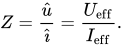
to calculate either the peak or the effective value of the current or the voltage.
In the special case of resonance, in which the both reactive resistances
- and
have the same value (), then the impedance will only be determined by .


The impedance specified in the datasheets often show typical curves for the different capacitance values. With increasing frequency as the impedance decreases down to a minimum. The lower the impedance, the more easily alternating currents can be passed through the capacitor. At the apex, the point of resonance, where XC has the same value than XL, the capacitor has the lowest impedance value. Here only the ESR determines the impedance. With frequencies above the resonance the impedance increases again due to the ESL of the capacitor. The capacitor becomes an inductance.
As shown in the graph, the higher capacitance values can fit the lower frequencies better while the lower capacitance values can fit better the higher frequencies.
Aluminum electrolytic capacitors have relatively good decoupling properties in the lower frequency range up to about 1 MHz due to their large capacitance values. This is the reason for using electrolytic capacitors in standard or switched-mode power supplies behind the rectifier for smoothing application.
Ceramic and film capacitors are already out of their smaller capacitance values suitable for higher frequencies up to several 100 MHz. They also have significantly lower parasitic inductance, making them suitable for higher frequency applications, due to their construction with end-surface contacting of the electrodes. To increase the range of frequencies, often an electrolytic capacitor is connected in parallel with a ceramic or film capacitor.[47]
Many new developments are targeted at reducing parasitic inductance (ESL). This increases the resonance frequency of the capacitor and, for example, can follow the constantly increasing switching speed of digital circuits. Miniaturization, especially in the SMD multilayer ceramic chip capacitors (MLCC), increases the resonance frequency. Parasitic inductance is further lowered by placing the electrodes on the longitudinal side of the chip instead of the lateral side. The "face-down" construction associated with multi-anode technology in tantalum electrolytic capacitors further reduced ESL. Capacitor families such as the so-called MOS capacitor or silicon capacitors offer solutions when capacitors at frequencies up to the GHz range are needed.
Inductance (ESL) and self-resonant frequency
ESL in industrial capacitors is mainly caused by the leads and internal connections used to connect the capacitor plates to the outside world. Large capacitors tend to have higher ESL than small ones because the distances to the plate are longer and every mm counts as an inductance.
For any discrete capacitor, there is a frequency above DC at which it ceases to behave as a pure capacitor. This frequency, where is as high as , is called the self-resonant frequency. The self-resonant frequency is the lowest frequency at which the impedance passes through a minimum. For any AC application the self-resonant frequency is the highest frequency at which capacitors can be used as a capacitive component.


This is critically important for decoupling high-speed logic circuits from the power supply. The decoupling capacitor supplies transient current to the chip. Without decouplers, the IC demands current faster than the connection to the power supply can supply it, as parts of the circuit rapidly switch on and off. To counter this potential problem, circuits frequently use multiple bypass capacitors—small (100 nF or less) capacitors rated for high frequencies, a large electrolytic capacitor rated for lower frequencies and occasionally, an intermediate value capacitor.
Ohmic losses, ESR, dissipation factor, and quality factor
The summarized losses in discrete capacitors are ohmic AC losses. DC losses are specified as "leakage current" or "insulating resistance" and are negligible for an AC specification. AC losses are non-linear, possibly depending on frequency, temperature, age or humidity. The losses result from two physical conditions:
- line losses including internal supply line resistances, the contact resistance of the electrode contact, line resistance of the electrodes, and in "wet" aluminum electrolytic capacitors and especially supercapacitors, the limited conductivity of liquid electrolytes and
- dielectric losses from dielectric polarization.
The largest share of these losses in larger capacitors is usually the frequency dependent ohmic dielectric losses. For smaller components, especially for wet electrolytic capacitors, conductivity of liquid electrolytes may exceed dielectric losses. To measure these losses, the measurement frequency must be set. Since commercially available components offer capacitance values cover 15 orders of magnitude, ranging from pF (10−12 F) to some 1000 F in supercapacitors, it is not possible to capture the entire range with only one frequency. IEC 60384-1 states that ohmic losses should be measured at the same frequency used to measure capacitance. These are:
- 100 kHz, 1 MHz (preferred) or 10 MHz for non-electrolytic capacitors with CR ≤ 1 nF:
- 1 kHz or 10 kHz for non-electrolytic capacitors with 1 nF < CR ≤ 10 μF
- 100/120 Hz for electrolytic capacitors
- 50/60 Hz or 100/120 Hz for non-electrolytic capacitors with CR > 10 μF
A capacitor's summarized resistive losses may be specified either as ESR, as a dissipation factor(DF, tan δ), or as quality factor (Q), depending on application requirements.
Capacitors with higher ripple current loads, such as electrolytic capacitors, are specified with equivalent series resistance ESR. ESR can be shown as an ohmic part in the above vector diagram. ESR values are specified in datasheets per individual type.

The losses of film capacitors and some class 2 ceramic capacitors are mostly specified with the dissipation factor tan δ. These capacitors have smaller losses than electrolytic capacitors and mostly are used at higher frequencies up to some hundred MHz. However the numeric value of the dissipation factor, measured at the same frequency, is independent of the capacitance value and can be specified for a capacitor series with a range of capacitance. The dissipation factor is determined as the tangent of the reactance () and the ESR, and can be shown as the angle δ between imaginary and the impedance axis.

If the inductance is small, the dissipation factor can be approximated as:


Capacitors with very low losses, such as ceramic Class 1 and Class 2 capacitors, specify resistive losses with a quality factor (Q). Ceramic Class 1 capacitors are especially suitable for LC resonant circuits with frequencies up to the GHz range, and precise high and low pass filters. For an electrically resonant system, Q represents the effect of electrical resistance and characterizes a resonator's bandwidth relative to its center or resonant frequency . Q is defined as the reciprocal value of the dissipation factor.


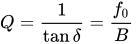
A high Q value is for resonant circuits a mark of the quality of the resonance.
Limiting current loads
A capacitor can act as an AC resistor, coupling AC voltage and AC current between two points. Every AC current flow through a capacitor generates heat inside the capacitor body. These dissipation power loss is caused by and is the squared value of the effective (RMS) current



The same power loss can be written with the dissipation factor as

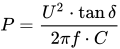
The internal generated heat has to be distributed to the ambient. The temperature of the capacitor, which is established on the balance between heat produced and distributed, shall not exceed the capacitors maximum specified temperature. Hence, the ESR or dissipation factor is a mark for the maximum power (AC load, ripple current, pulse load, etc.) a capacitor is specified for.
AC currents may be a:
- ripple current—an effective (RMS) AC current, coming from an AC voltage superimposed of a DC bias, a
- pulse current—an AC peak current, coming from a voltage peak, or an
- AC current—an effective (RMS) sinusoidal current
Ripple and AC currents mainly warms the capacitor body. By this currents internal generated temperature influences the breakdown voltage of the dielectric. Higher temperature lower the voltage proof of all capacitors. In wet electrolytic capacitors higher temperatures force the evaporation of electrolytes, shortening the life time of the capacitors. In film capacitors higher temperatures may shrink the plastic film changing the capacitor's properties.
Pulse currents, especially in metallized film capacitors, heat the contact areas between end spray (schoopage) and metallized electrodes. This may reduce the contact to the electrodes, heightening the dissipation factor.
For safe operation, the maximal temperature generated by any AC current flow through the capacitor is a limiting factor, which in turn limits AC load, ripple current, pulse load, etc.
Ripple current
A "ripple current" is the RMS value of a superimposed AC current of any frequency and any waveform of the current curve for continuous operation at a specified temperature. It arises mainly in power supplies (including switched-mode power supplies) after rectifying an AC voltage and flows as charge and discharge current through the decoupling or smoothing capacitor. The "rated ripple current" shall not exceed a temperature rise of 3, 5 or 10 °C, depending on the capacitor type, at the specified maximum ambient temperature.
Ripple current generates heat within the capacitor body due to the ESR of the capacitor. The components of capacitor ESR are: the dielectric losses caused by the changing field strength in the dielectric, the resistance of the supply conductor, and the resistance of the electrolyte. For an electric double layer capacitor (ELDC) these resistance values can be derived from a Nyquist plot of the capacitor's complex impedance.[51]
ESR is dependent on frequency and temperature. For ceramic and film capacitors in generally ESR decreases with increasing temperatures but heighten with higher frequencies due to increasing dielectric losses. For electrolytic capacitors up to roughly 1 MHz ESR decreases with increasing frequencies and temperatures.
The types of capacitors used for power applications have a specified rated value for maximum ripple current. These are primarily aluminum electrolytic capacitors, and tantalum as well as some film capacitors and Class 2 ceramic capacitors.
Aluminum electrolytic capacitors, the most common type for power supplies, experience shorter life expectancy at higher ripple currents. Exceeding the limit tends to result in explosive failure.
Tantalum electrolytic capacitors with solid manganese dioxide electrolyte are also limited by ripple current. Exceeding their ripple limits tends to shorts and burning components.
For film and ceramic capacitors, normally specified with a loss factor tan δ, the ripple current limit is determined by temperature rise in the body of approximately 10 °C. Exceeding this limit may destroy the internal structure and cause shorts.
Pulse current
The rated pulse load for a certain capacitor is limited by the rated voltage, the pulse repetition frequency, temperature range and pulse rise time. The "pulse rise time" , represents the steepest voltage gradient of the pulse (rise or fall time) and is expressed in volts per μs (V/μs).

The rated pulse rise time is also indirectly the maximum capacity of an applicable peak current . The peak current is defined as:

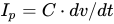
where: is in A; in μF; in V/μs
The permissible pulse current capacity of a metallized film capacitor generally allows an internal temperature rise of 8 to 10 K.
In the case of metallized film capacitors, pulse load depends on the properties of the dielectric material, the thickness of the metallization and the capacitor's construction, especially the construction of the contact areas between the end spray and metallized electrodes. High peak currents may lead to selective overheating of local contacts between end spray and metallized electrodes which may destroy some of the contacts, leading to increasing ESR.
For metallized film capacitors, so-called pulse tests simulate the pulse load that might occur during an application, according to a standard specification. IEC 60384 part 1, specifies that the test circuit is charged and discharged intermittently. The test voltage corresponds to the rated DC voltage and the test comprises 10000 pulses with a repetition frequency of 1 Hz. The pulse stress capacity is the pulse rise time. The rated pulse rise time is specified as 1/10 of the test pulse rise time.
The pulse load must be calculated for each application. A general rule for calculating the power handling of film capacitors is not available because of vendor-related internal construction details. To prevent the capacitor from overheating the following operating parameters have to be considered:
- peak current per μF
- Pulse rise or fall time dv/dt in V/μs
- relative duration of charge and discharge periods (pulse shape)
- maximum pulse voltage (peak voltage)
- peak reverse voltage;
- Repetition frequency of the pulse
- Ambient temperature
- Heat dissipation (cooling)
Higher pulse rise times are permitted for pulse voltage lower than the rated voltage.
Examples for calculations of individual pulse loads are given by many manufactures, e.g. WIMA[52] and Kemet.[53]
AC current

An AC load only can be applied to a non-polarized capacitor. Capacitors for AC applications are primarily film capacitors, metallized paper capacitors, ceramic capacitors and bipolar electrolytic capacitors.
The rated AC load for an AC capacitor is the maximum sinusoidal effective AC current (rms) which may be applied continuously to a capacitor within the specified temperature range. In the datasheets the AC load may be expressed as
- rated AC voltage at low frequencies,
- rated reactive power at intermediate frequencies,
- reduced AC voltage or rated AC current at high frequencies.

The rated AC voltage for film capacitors is generally calculated so that an internal temperature rise of 8 to 10 K is the allowed limit for safe operation. Because dielectric losses increase with increasing frequency, the specified AC voltage has to be derated at higher frequencies. Datasheets for film capacitors specify special curves for derating AC voltages at higher frequencies.
If film capacitors or ceramic capacitors only have a DC specification, the peak value of the AC voltage applied has to be lower than the specified DC voltage.
AC loads can occur in AC motor run capacitors, for voltage doubling, in snubbers, lighting ballast and for PFC for phase shifting to improve transmission network stability and efficiency, which is one of the most important applications for large power capacitors. These mostly large PP film or metallized paper capacitors are limited by the rated reactive power VAr.
Bipolar electrolytic capacitors, to which an AC voltage may be applicable, are specified with a rated ripple current.
Insulation resistance and self-discharge constant
The resistance of the dielectric is finite, leading to some level of DC "leakage current" that causes a charged capacitor to lose charge over time. For ceramic and film capacitors, this resistance is called "insulation resistance Rins". This resistance is represented by the resistor Rins in parallel with the capacitor in the series-equivalent circuit of capacitors. Insulation resistance must not be confused with the outer isolation of the component with respect to the environment.
The time curve of self-discharge over insulation resistance with decreasing capacitor voltage follows the formula

With stored DC voltage and self-discharge constant

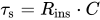
Thus, after voltage drops to 37% of the initial value.

The self-discharge constant is an important parameter for the insulation of the dielectric between the electrodes of ceramic and film capacitors. For example, a capacitor can be used as the time-determining component for time relays or for storing a voltage value as in a sample and hold circuits or operational amplifiers.
Class 1 ceramic capacitors have an insulation resistance of at least 10 GΩ, while class 2 capacitors have at least 4 GΩ or a self-discharge constant of at least 100 s. Plastic film capacitors typically have an insulation resistance of 6 to 12 GΩ. This corresponds to capacitors in the uF range of a self-discharge constant of about 2000–4000 s.[54]
Insulation resistance respectively the self-discharge constant can be reduced if humidity penetrates into the winding. It is partially strongly temperature dependent and decreases with increasing temperature. Both decrease with increasing temperature.
In electrolytic capacitors, the insulation resistance is defined as leakage current.
Leakage current


For electrolytic capacitors the insulation resistance of the dielectric is termed "leakage current". This DC current is represented by the resistor Rleak in parallel with the capacitor in the series-equivalent circuit of electrolytic capacitors. This resistance between the terminals of a capacitor is also finite. Rleak is lower for electrolytics than for ceramic or film capacitors.
The leakage current includes all weak imperfections of the dielectric caused by unwanted chemical processes and mechanical damage. It is also the DC current that can pass through the dielectric after applying a voltage. It depends on the interval without voltage applied (storage time), the thermic stress from soldering, on voltage applied, on temperature of the capacitor, and on measuring time.
The leakage current drops in the first minutes after applying DC voltage. In this period the dielectric oxide layer can self-repair weaknesses by building up new layers. The time required depends generally on the electrolyte. Solid electrolytes drop faster than non-solid electrolytes but remain at a slightly higher level.
The leakage current in non-solid electrolytic capacitors as well as in manganese oxide solid tantalum capacitors decreases with voltage-connected time due to self-healing effects. Although electrolytics leakage current is higher than current flow over insulation resistance in ceramic or film capacitors, the self-discharge of modern non solid electrolytic capacitors takes several weeks.
A particular problem with electrolytic capacitors is storage time. Higher leakage current can be the result of longer storage times. These behaviors are limited to electrolytes with a high percentage of water. Organic solvents such as GBL do not have high leakage with longer storage times.
Leakage current is normally measured 2 or 5 minutes after applying rated voltage.
Microphonics
All ferroelectric materials exhibit a piezoelectric effect. Because Class 2 ceramic capacitors use ferroelectric ceramics dielectric, these types of capacitors may have electrical effects called microphonics. Microphonics (microphony) describes how electronic components transform mechanical vibrations into an undesired electrical signal (noise).[55] The dielectric may absorb mechanical forces from shock or vibration by changing thickness and changing the electrode separation, affecting the capacitance, which in turn induces an AC current. The resulting interference is especially problematic in audio applications, potentially causing feedback or unintended recording.
In the reverse microphonic effect, varying the electric field between the capacitor plates exerts a physical force, turning them into an audio speaker. High current impulse loads or high ripple currents can generate audible sound from the capacitor itself, draining energy and stressing the dielectric.[56]
Dielectric absorption (soakage)
Dielectric absorption occurs when a capacitor that has remained charged for a long time discharges only incompletely when briefly discharged. Although an ideal capacitor would reach zero volts after discharge, real capacitors develop a small voltage from time-delayed dipole discharging, a phenomenon that is also called dielectric relaxation, "soakage" or "battery action".
In many applications of capacitors dielectric absorption is not a problem but in some applications, such as long-time-constantintegrators, sample-and-hold circuits, switched-capacitor analog-to-digital converters, and very low-distortion filters, the capacitor must not recover a residual charge after full discharge, so capacitors with low absorption are specified.[59] The voltage at the terminals generated by the dielectric absorption may in some cases possibly cause problems in the function of an electronic circuit or can be a safety risk to personnel. In order to prevent shocks most very large capacitors are shipped with shorting wires that need to be removed before they are used.[60]
Energy density
The capacitance value depends on the dielectric material (ε), the surface of the electrodes (A) and the distance (d) separating the electrodes and is given by the formula of a plate capacitor:

The separation of the electrodes and the voltage proof of the dielectric material defines the breakdown voltage of the capacitor. The breakdown voltage is proportional to the thickness of the dielectric.
Theoretically, given two capacitors with the same mechanical dimensions and dielectric, but one of them have half the thickness of the dielectric. With the same dimensions this one could place twice the parallel-plate area inside. This capacitor has theoretically 4 times the capacitance as the first capacitor but half of the voltage proof.
Since the energy density stored in a capacitor is given by:

thus a capacitor having a dielectric half as thick as another has 4 times higher capacitance but 1⁄2 voltage proof, yielding an equal maximum energy density.
Therefore, dielectric thickness does not affect energy density within a capacitor of fixed overall dimensions. Using a few thick layers of dielectric can support a high voltage, but low capacitance, while thin layers of dielectric produce a low breakdown voltage, but a higher capacitance.
This assumes that neither the electrode surfaces nor the permittivity of the dielectric change with the voltage proof. A simple comparison with two existing capacitor series can show whether reality matches theory. The comparison is easy, because the manufacturers use standardized case sizes or boxes for different capacitance/voltage values within a series.
In reality modern capacitor series do not fit the theory. For electrolytic capacitors the sponge-like rough surface of the anode foil gets smoother with higher voltages, decreasing the surface area of the anode. But because the energy increases squared with the voltage, and the surface of the anode decreases lesser than the voltage proof, the energy density increases clearly. For film capacitors the permittivity changes with dielectric thickness and other mechanical parameters so that the deviation from the theory has other reasons.[63]
Comparing the capacitors from the table with a supercapacitor, the highest energy density capacitor family. For this, the capacitor 25 F/2.3 V in dimensions D × H = 16 mm × 26 mm from Maxwell HC Series, compared with the electrolytic capacitor of approximately equal size in the table. This supercapacitor has roughly 5000 times higher capacitance than the 4700/10 electrolytic capacitor but 1⁄4 of the voltage and has about 66,000 mWs (0.018 Wh) stored electrical energy,[64] approximately 100 times higher energy density (40 to 280 times) than the electrolytic capacitor.
Long time behavior, aging
Electrical parameters of capacitors may change over time during storage and application. The reasons for parameter changings are different, it may be a property of the dielectric, environmental influences, chemical processes or drying-out effects for non-solid materials.
Aging

In ferroelectric Class 2 ceramic capacitors, capacitance decreases over time. This behavior is called "aging". This aging occurs in ferroelectric dielectrics, where domains of polarization in the dielectric contribute to the total polarization. Degradation of polarized domains in the dielectric decreases permittivity and therefore capacitance over time.[65][66] The aging follows a logarithmic law. This defines the decrease of capacitance as constant percentage for a time decade after the soldering recovery time at a defined temperature, for example, in the period from 1 to 10 hours at 20 °C. As the law is logarithmic, the percentage loss of capacitance will twice between 1 h and 100 h and 3 times between 1 h and 1,000 h and so on. Aging is fastest near the beginning, and the absolute capacitance value stabilizes over time.
The rate of aging of Class 2 ceramic capacitors depends mainly on its materials. Generally, the higher the temperature dependence of the ceramic, the higher the aging percentage. The typical aging of X7R ceramic capacitors is about 2.5% per decade.[67] The aging rate of Z5U ceramic capacitors is significantly higher and can be up to 7% per decade.
The aging process of Class 2 ceramic capacitors may be reversed by heating the component above the Curie point.
Class 1 ceramic capacitors and film capacitors do not have ferroelectric-related aging. Environmental influences such as higher temperature, high humidity and mechanical stress can, over a longer period, lead to a small irreversible change in the capacitance value sometimes called aging, too.
The change of capacitance for P 100 and N 470 Class 1 ceramic capacitors is lower than 1%, for capacitors with N 750 to N 1500 ceramics it is ≤ 2%. Film capacitors may lose capacitance due to self-healing processes or gain it due to humidity influences. Typical changes over 2 years at 40 °C are, for example, ±3% for PE film capacitors and ±1% PP film capacitors.
Life time

Electrolytic capacitors with non-solid electrolyte age as the electrolyte evaporates. This evaporation depends on temperature and the current load the capacitors experience. Electrolyte escape influences capacitance and ESR. Capacitance decreases and the ESR increases over time. In contrast to ceramic, film and electrolytic capacitors with solid electrolytes, "wet" electrolytic capacitors reach a specified "end of life" reaching a specified maximum change of capacitance or ESR. End of life, "load life" or "lifetime" can be estimated either by formula or diagrams[68] or roughly by a so-called "10-degree-law". A typical specification for an electrolytic capacitor states a lifetime of 2,000 hours at 85 °C, doubling for every 10 degrees lower temperature, achieving lifespan of approximately 15 years at room temperature.
Supercapacitors also experience electrolyte evaporation over time. Estimation is similar to wet electrolytic capacitors. Additional to temperature the voltage and current load influence the life time. Lower voltage than rated voltage and lower current loads as well as lower temperature extend the life time.
Failure rate

Capacitors are reliable components with low failure rates, achieving life expectancies of decades under normal conditions. Most capacitors pass a test at the end of production similar to a "burn in", so that early failures are found during production, reducing the number of post-shipment failures.
Reliability for capacitors is usually specified in numbers of Failures In Time (FIT) during the period of constant random failures. FIT is the number of failures that can be expected in one billion component-hours of operation at fixed working conditions (e.g. 1000 devices for 1 million hours, or 1 million devices for 1000 hours each, at 40 °C and 0.5 UR). For other conditions of applied voltage, current load, temperature, mechanical influences and humidity the FIT can recalculated with terms standardized for industrial[69] or military[70] contexts.
Additional information
Soldering
Capacitors may experience changes to electrical parameters due to environmental influences like soldering, mechanical stress factors (vibration, shock) and humidity. The greatest stress factor is soldering. The heat of the solder bath, especially for SMD capacitors, can cause ceramic capacitors to change contact resistance between terminals and electrodes; in film capacitors, the film may shrink, and in wet electrolytic capacitors the electrolyte may boil. A recovery period enables characteristics to stabilize after soldering; some types may require up to 24 hours. Some properties may change irreversibly by a few per cent from soldering.
Electrolytic behavior from storage or disuse
Electrolytic capacitors with non-solid electrolyte are "aged" during manufacturing by applying rated voltage at high temperature for a sufficient time to repair all cracks and weaknesses that may have occurred during production. Some electrolytes with a high water content react quite aggressively or even violently with unprotected aluminum. This leads to a "storage" or "disuse" problem of electrolytic capacitors manufactured before the 1980s. Chemical processes weaken the oxide layer when these capacitors are not used for too long, leading to failure or poor performance such as excessive leakage. New electrolytes with "inhibitors" or "passivators" were developed during the 1980s to lessen this problem.[71][72]
"Pre-conditioning" may be recommended for electrolytic capacitors with non-solid electrolyte, even those manufactured recently, that have not been in use for an extended period. In pre-conditioning a voltage is applied across the capacitor and a deliberately limited current is passed through the capacitor. Sending a limited current through the capacitor repairs oxide layers damaged during the period of disuse. The applied voltage is lower than or equal to the capacitor's rated voltage. Current may be limited using, for instance, a series resistor. Pre-conditioning is stopped once leakage current is below some acceptable level at the desired voltage. As of 2015 one manufacturer indicates that pre-conditioning may be usefully carried out for capacitors with non-solid electrolytes that have been in storage for more than 1 to 10 years, the maximum storage time depending on capacitor type.[73]
IEC/EN standards
The tests and requirements to be met by capacitors for use in electronic equipment for approval as standardized types are set out in the generic specification IEC/EN 60384–1 in the following sections.[74]
Generic specification
- IEC/EN 60384-1—Fixed capacitors for use in electronic equipment
Ceramic capacitors
- IEC/EN 60384-8—Fixed capacitors of ceramic dielectric, Class 1
- IEC/EN 60384-9—Fixed capacitors of ceramic dielectric, Class 2
- IEC/EN 60384-21—Fixed surface mount multilayer capacitors of ceramic dielectric, Class 1
- IEC/EN 60384-22—Fixed surface mount multilayer capacitors of ceramic dielectric, Class 2
Film capacitors
- IEC/EN 60384-2—Fixed metallized polyethylene-terephthalate film dielectric d.c. capacitors
- IEC/EN 60384-11—Fixed polyethylene-terephthalate film dielectric metal foil d.c. capacitors
- IEC/EN 60384-13—Fixed polypropylene film dielectric metal foil d.c. capacitors
- IEC/EN 60384-16—Fixed metallized polypropylene film dielectric d.c. capacitors
- IEC/EN 60384-17—Fixed metallized polypropylene film dielectric a.c. and pulse
- IEC/EN 60384-19—Fixed metallized polyethylene-terephthalate film dielectric surface mount d.c. capacitors
- IEC/EN 60384-20—Fixed metallized polyphenylene sulfide film dielectric surface mount d.c. capacitors
- IEC/EN 60384-23—Fixed metallized polyethylene naphthalate film dielectric chip d.c. capacitors
Electrolytic capacitors
- IEC/EN 60384-3—Surface mount fixed tantalum electrolytic capacitors with manganese dioxide solid electrolyte
- IEC/EN 60384-4—Aluminium electrolytic capacitors with solid (MnO2) and non-solid electrolyte
- IEC/EN 60384-15—Fixed tantalum capacitors with non-solid and solid electrolyte
- IEC/EN 60384-18—Fixed aluminium electrolytic surface mount capacitors with solid (MnO2) and non-solid electrolyte
- IEC/EN 60384-24—Surface mount fixed tantalum electrolytic capacitors with conductive polymer solid electrolyte
- IEC/EN 60384-25—Surface mount fixed aluminium electrolytic capacitors with conductive polymer solid electrolyte
- IEC/EN 60384-26—Fixed aluminium electrolytic capacitors with conductive polymer solid electrolyte
Supercapacitors
- IEC/EN 62391-1—Fixed electric double-layer capacitors for use in electric and electronic equipment – Part 1: Generic specification
- IEC/EN 62391-2—Fixed electric double-layer capacitors for use in electronic equipment – Part 2: Sectional specification – Electric double-layer capacitors for power application
Capacitor symbols
Markings
Imprinted
Capacitors, like most other electronic components and if enough space is available, have imprinted markings to indicate manufacturer, type, electrical and thermal characteristics, and date of manufacture. If they are large enough the capacitor is marked with:
- manufacturer's name or trademark;
- manufacturer's type designation;
- polarity of the terminations (for polarized capacitors)
- rated capacitance;
- tolerance on rated capacitance
- rated voltage and nature of supply (AC or DC)
- climatic category or rated temperature;
- year and month (or week) of manufacture;
- certification marks of safety standards (for safety EMI/RFI suppression capacitors)
Polarized capacitors have polarity markings, usually "−" (minus) sign on the side of the negative electrode for electrolytic capacitors or a stripe or "+" (plus) sign, see #Polarity marking. Also, the negative lead for leaded "wet" e-caps is usually shorter.
Smaller capacitors use a shorthand notation. The most commonly used format is: XYZ J/K/M VOLTS V, where XYZ represents the capacitance (calculated as XY × 10Z pF), the letters J, K or M indicate the tolerance (±5%, ±10% and ±20% respectively) and VOLTS V represents the working voltage.
Examples:
- 105K 330 V implies a capacitance of 10 × 105 pF = 1 μF (K = ±10%) with a working voltage of 330 V.
- 473M 100 V implies a capacitance of 47 × 103 pF = 47 nF (M = ±20%) with a working voltage of 100 V.
Capacitance, tolerance and date of manufacture can be indicated with a short code specified in IEC/EN 60062. Examples of short-marking of the rated capacitance (microfarads): μ47 = 0.47 μF, 4μ7 = 4.7 μF, 47μ = 47 μF
The date of manufacture is often printed in accordance with international standards.
- Version 1: coding with year/week numeral code, "1208" is "2012, week number 8".
- Version 2: coding with year code/month code. The year codes are: "R" = 2003, "S"= 2004, "T" = 2005, "U" = 2006, "V" = 2007, "W" = 2008, "X" = 2009, "A" = 2010, "B" = 2011, "C" = 2012, "D" = 2013, etc. Month codes are: "1" to "9" = Jan. to Sept., "O" = October, "N" = November, "D" = December. "X5" is then "2009, May"
For very small capacitors like MLCC chips no marking is possible. Here only the traceability of the manufacturers can ensure the identification of a type.
Colour coding
As of 2013 Capacitors do not use color coding.
Polarity marking
- Polarity marking


Aluminum e-caps with non-solid electrolyte have a polarity marking at the cathode (minus) side. Aluminum, tantalum, and niobium e-caps with solid electrolyte have a polarity marking at the anode (plus) side. Supercapacitors are marked at the minus side.
 Rectangular polymer capacitors, tantalum as well as aluminum, have a polarity marking at the anode (plus) side
 Cylindrical polymer capacitors have a polarity marking at the cathode (minus) side
 Supercapacitors are marked at the cathode (minus) side
Market segments
Discrete capacitors today are industrial products produced in very large quantities for use in electronic and in electrical equipment. Globally, the market for fixed capacitors was estimated at US$18 billion in 2008 for 1.4 trillion pieces.[75] This market is dominated by ceramic capacitors with estimate of approximately one trillion items per year.[76]
Detailed estimated figures in value for the main capacitor families are:
- Ceramic capacitors—US$8.3 billion (46%);
- Aluminum electrolytic capacitors—US$3.9 billion (22%);
- Film capacitors and Paper capacitors—US$2.6 billion, (15%);
- Tantalum electrolytic capacitors—US$2.2 billion (12%);
- Super capacitors (Double-layer capacitors)—US$0.3 billion (2%); and
- Others like silver mica and vacuum capacitors—US$0.7 billion (3%).
All other capacitor types are negligible in terms of value and quantity compared with the above types.
See also
References
- ^ abcNamisnyk, Adam Marcus (23 June 2003). "A Survey of Electrochemical Supercapacitor Technology"(PDF). Archived from the original(PDF) on 22 December 2014. Retrieved 2011-06-24.
- ^WIMA, Characteristics of Metallized Film Capacitors in Comparison with Other Dielectrics [1]Archived 2012-11-05 at the Wayback Machine
- ^"TDK Europe – General Technical Information"(PDF).
- ^Tomáš Kárník, AVX, NIOBIUM OXIDE FOR CAPACITOR MANUFACTURING, METAL 2008, 13. –15. 5. 2008, Hradec nad Moravicí PDF. Archived 2016-03-05 at the Wayback Machine.
- ^"Holystone, Capacitor Dielectric Comparison, Technical Note 3"(PDF).
- ^P. Bettacchi, D. Montanari, D. Zanarini, D. Orioli, G. Rondelli, A. Sanua, KEMET Electronics Power Film Capacitors for Industrial ApplicationsArchived 2014-03-02 at the Wayback Machine
- ^ abS. P. Murarka; Moshe Eisenberg; A. K. Sinha (2003), Interlayer dielectrics for semiconductor technologies (in German), Academic Press, pp. 338–339, ISBN 9780125112215
- ^Vishay. "Vishay – Capacitors – RFI Safety Rated X/Y". www.vishay.com.
- ^"X2Y Attenuators – Home". www.x2y.com.
- ^"Three-terminal Capacitor Structure, Murata".
- ^"Murata, Three-terminal Capacitor Structure, No.TE04EA-1.pdf 98.3.20"(PDF).
- ^"Vishay, Ceramic RF-Power Capacitors"(PDF). Archived from the original(PDF) on 2019-07-13. Retrieved 2012-12-14.
- ^Vishay. "Capacitors – RF Power". Vishay. Archived from the original on 2012-08-14. Retrieved 2013-03-09.
- ^Passive component magazine, November/December 2005, F. Jacobs, p. 29 ff ,Polypropylene Capacitor Film Resin. Archived 2016-03-04 at the Wayback Machine.
- ^"Capacitor Reports | Resistor Reports | Electronic Analysis | Dennis Zogbi | Paumanok Publications". Paumanokgroup.com. 2013-11-08. Retrieved 2014-03-02.
- ^"WIMA Radio Interference Suppression (RFI) Capacitors". www.wima.com.
- ^"WIMA Snubber Capacitors". www.wima.com.
- ^"Motor-Run Capacitors online". www.motor-runcapacitorsonline.com.
- ^"Sorry, the requested page could not be found. – TDK Europe"(PDF). www.epcos.com.
- ^Chenxi, Rizee (15 May 2014). "2017 Tendency For Electronic Components Market". www.wellpcb.com. WellPCB. Retrieved 29 May 2017.
- ^U. Merker, K. Wussow, W. Lövenich, H. C. Starck GmbH, New Conducting Polymer Dispersions for Solid Electrolyte Capacitors, PDF. Archived 2016-03-04 at the Wayback Machine.
- ^"CDE, Motor Start Capacitors"(PDF).
- ^"Rubycon, Aluminum Electrolytic Capacitors for Strobe Flash"(PDF). Archived from the original(PDF) on 2020-12-02. Retrieved 2012-12-14.
- ^"Electrolytic Capacitors". www.ftcap.de.
- ^ abcConway, B. E. (1999). Electrochemical Supercapacitors: Scientific Fundamentals and Technological Applications. Berlin, Germany: Springer. ISBN 978-0306457364. Retrieved November 21, 2014. see also Brian E. Conway in Electrochemistry Encyclopedia: Electrochemical Capacitors – Their Nature, Function and Applications. Archived 2012-08-13 at the Wayback Machine.
- ^Marin S. Halper, James C. Ellenbogen (March 2006). Supercapacitors: A Brief Overview(PDF) (Technical report). MITRE Nanosystems Group. Retrieved 2013-04-02.
- ^Frackowiak, Elzbieta; Béguin, François (2001). "Carbon materials for the electrochemical storage of energy in capacitors". Carbon. 39 (6): 937–950. Bibcode:2001Carbo..39..937F. doi:10.1016/S0008-6223(00)00183-4.
- ^Sur, Ujjal Kumar (2012-01-27). Recent Trend in Electrochemical Science and Technology. IntechOpen. ISBN 978-953-307-830-4.
- ^"Elton". Archived from the original on 2013-06-23. Retrieved 2013-08-15.
- ^"AC Safety Capacitors"Archived 2015-10-04 at the Wayback Machine.
- ^"Across-the-line Capacitors, Antenna-coupling Components, Line-bypass Components and Fixed Capacitors for Use in Electronic Equipment". UL Online Certification Directory.
- ^Douglas Edson and David Wadler. "A New Low ESR Fused Solid Tantalum Capacitor". Archived 2013-08-06 at the Wayback Machine.
- ^ DeMatos, H. "Design of an Internal Fuse for a High-Frequency Solid Tantalum Capacitor". 1980. doi: 10.1109/TCHMT.1980.1135610.
- ^ Tagare. "Electrical Power Capacitors". 2001.
- ^ Hemant Joshi. "Residential, Commercial and Industrial Electrical Systems: Equipment and selection". 2008. section 21.2.1: "Internal fuse". p. 446.
- ^"3D Silicon Capacitors". www.ipdia.com. Archived from the original on 2019-07-01. Retrieved 2012-12-14.
- ^Harry Lythall – SM0VPO. "Gimmick Capacitors". Archived 2011-06-13 at the Wayback Machine.
- ^ Darren Ashby, Bonnie Baker, Ian Hickman, Walt Kester, Robert Pease, Tim Williams, Bob Zeidman. "Circuit Design: Know It All". 2011. p. 201.
- ^ Robert A. Pease. "Troubleshooting Analog Circuits". 1991. p. 20.
- ^ Robert A. Pease. "Troubleshooting analog circuits, part 2: The right equipment is essential for effective troubleshooting". EDN January 19, 1989. p. 163.
- ^ David Cripe, NM0S and Four State QRP Group. "Instruction Manual Cyclone 40: 40 Meter Transceiver". 2013. p. 17.
- ^"Polystyrene capacitor advantages and disadvantages". Retrieved 14 February 2016.
- ^"Vishay, Wet Electrolyte Tantalum Capacitors, Introduction"(PDF). Archived from the original(PDF) on 2015-05-13. Retrieved 2012-12-14.
- ^Self-healing Characteristics of Solid Electrolytic Capacitor with Polypyrrole Electrolyte, Yamamoto Hideo [2].
- ^"DRILCO, S.L. – INICIO"(PDF). www.electrico.drilco.net.
- ^"AVX, Performance Characteristics of Multilayer Glass Capacitors"(PDF). Archived from the original(PDF) on 2015-09-23. Retrieved 2012-12-14.
- ^Murata: Basics of capacitors, lesson 2 Includes graph showing impedance as a function of frequency for different capacitor types; electrolytics are the only ones with a large component due to ESR
- ^Vishay. "Vishay – Vishay Introduces First Silicon-Based, Surface-Mount RF Capacitor in 0603 Case Size". www.vishay.com.
- ^Infotech, Aditya. "Chip Mica Capacitors". www.simicelectronics.com. Archived from the original on 2012-12-19. Retrieved 2012-12-14.
- ^"AVX, NP0, 1000 pF 100 V, 0805, Q >= 1000 (1 MHz)"(PDF). Archived from the original(PDF) on 2012-12-24. Retrieved 2012-12-14.
- ^Mei, Munteshari, Lau, Dunn, and Pilon. "Physical Interpretations of Nyquist Plots for ELDC Electrodes and Devices"(PDF). Retrieved 2021-02-04.
{{cite web}}: CS1 maint: multiple names: authors list (link) Journal Phys. Chemistry C 2018, 122, 194−206. - ^"WIMA". www.wima.de. Archived from the original on 2012-11-05. Retrieved 2012-12-14.
- ^"General Information DC Film Capacitors"(PDF). www.kemet.com.
- ^"WIMA". www.wima.de. Archived from the original on 2012-11-04. Retrieved 2012-12-14.
- ^"Capacitors for Reduced Micro phonics and Sound Emission"(PDF). www.kemet.com. Archived from the original(PDF) on 2019-04-02. Retrieved 2017-06-02.
- ^Are your military ceramic capacitors subject to the piezoelectric effect?Archived June 19, 2012, at the Wayback Machine
- ^"Kemet, Polymer Tantalum Chip Capacitors"(PDF). Archived from the original(PDF) on 2014-11-23. Retrieved 2012-12-14.
- ^AVX, ANALYSIS OF SOLID TANTALUM CAPACITOR LEAKAGE CURRENTArchived August 6, 2013, at the Wayback Machine
- ^Bob Pease (1982), "Understand Capacitor Soakage to Optimize Analog Systems" [3]. Archived 2007-10-12 at the Wayback Machine.
- ^* "Modeling Dielectric Absorption in Capacitors", by Ken Kundert
- ^"NCC, KME series"(PDF).
- ^"KEMET General Purpose Pulse-and-DC-Transient-Suppression Capacitors"(PDF). www.kemet.com.
- ^Ralph M. Kerrigan, NWL Capacitor Division, Metallized Polypropylene Film Energy Storage Capacitors For Low Pulse Duty. Archived 2013-09-29 at the Wayback Machine.
- ^"Maxwell Ultracapacitors: Enabling Energy's Future". Maxwell Technologies.
- ^Plessner, K W (1956), "Ageing of the Dielectric Properties of Barium Titanate Ceramics", Proceedings of the Physical Society. Section B (in German), vol. 69, no. 12, pp. 1261–1268, Bibcode:1956PPSB...69.1261P, doi:10.1088/0370-1301/69/12/309
- ^Takaaki Tsurumi & Motohiro Shono & Hirofumi Kakemoto & Satoshi Wada & Kenji Saito & Hirokazu Chazono, Mechanism of capacitance aging under DC-bias field in X7R-MLCCs Published online: 23 March 2007, # Springer Science + Business Media, LLC 2007 [4]
- ^Christopher England, Johanson dielectrics, Ceramic Capacitor Aging Made Simple [5]Archived 2012-12-26 at the Wayback Machine
- ^Dr. Arne Albertsen, Jianghai Europe, Electrolytic Capacitor Lifetime EstimationArchived 2013-01-08 at the Wayback Machine
- ^IEC/EN 61709, Electric components. Reliability. Reference conditions for failure rates and stress models for conversion
- ^MIL-HDBK-217F Reliability Prediction of Electronic Equipment
- ^J. L. Stevens, T. R. Marshall, A. C. Geiculescu M., C. R. Feger, T. F. Strange, Carts USA 2006, The Effects of Electrolyte Composition on the Deformation Characteristics of Wet Aluminum ICD CapacitorsArchived 2014-11-26 at the Wayback Machine
- ^Alfonso Berduque, Zongli Dou, Rong Xu, BHC Components Limited (KEMET), pdf Electrochemical Studies for Aluminium Electrolytic Capacitor Applications: Corrosion Analysis of Aluminium in Ethylene Glycol-Based Electrolytes. Archived 2014-02-20 at the Wayback Machine.
- ^Vishay BCcomponents, Revision: 10-May-12, Document Number: 28356, Introduction Aluminum Capacitors, paragraph "Storage"Archived 2016-01-26 at the Wayback Machine
- ^"Beuth Verlag – Normen und Fachliteratur seit 1924". www.beuth.de.
- ^"Electronic Capacitors market report". Archived from the original on 2010-02-12.
- ^J. Ho, T. R. Jow, S. Boggs, Historical Introduction to Capacitor Technology. Archived 2016-12-05 at the Wayback Machine.
External links

- Spark Museum (von Kleist and Musschenbroek)
- Modeling Dielectric Absorption in Capacitors
- A different view of all this capacitor stuff
- Images of different types of capacitors
- Overview of different capacitor types
- Capsite 2015 Introduction to capacitors
- condensadores


